Northeastern Electric Racing: 2024 Chassis Manufacturing


Chassis Jig Design
Jig Design Concept Overview
The welding jig for the chassis needed to fix all tubes in their deisgned psotions, remain structurally rigid during welding, and be easy to manufacture.
My jig design used sets of interlocking planar jigs in two directions and a base with dowel pins to fix all tubes. The result was a network of jigs runnign horizontally and vertically along the chassis, fixing all tubes in place. I chose to use planar sheets so the jig parts could all be lasercut or CNC cut.
As a note, I did not design all of the jigs shown to the left. However I researched and chose this design concept, designing the first revision of all pegboards and primary/secondary jigs.
Pegboards
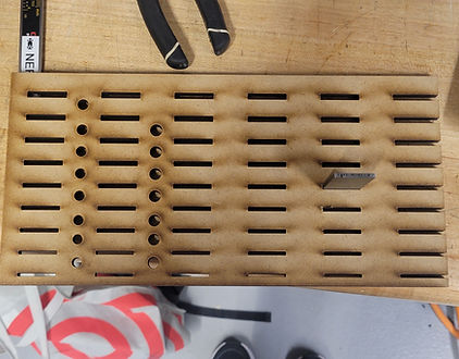
I used pegboards to make vertical planar faces along the chassis. This design used steel dowel pins to precisesly position tubes. A planar jig was used to locate all of the dowel pins, and consisted of two layers made of sheet steel and MDF. Steel was used as the top layer for fire safety, and formaldahyde-free MDF was used on the bottom to increase sheet thickness, minimizing dowel pin misalignment.

Manufactured Pegboard
Primary/Secondary Jigs

Primary jigs located and fixed all tubes in the chassis. Using large planar sheets minimized the jig count and served to locate the tubes relative to eachother. These jigs were cut from sheet steel for rigidity and easy manufacturing.
Secondary jigs interlocked with the primary jigs to eliminate bending&deflection. These jigs were also cut out of sheet steel and two were used in parallel to keep primary jigs from twisting in the secondary jigs.

Primary Jig
Secondary Jig
Material Selection/Sourcing Outcomes
When looking for jig materials, we were going to use MetalsDepot for all the sheet metal. I researched a other vendors to compare prices and found a local vendor that was 25% cheaper than our original supplier, reducing jig cost.
Much of the team was opposed to using MDF because most MDF compounds contain formaldahyde, wich releases as a toxic gas when burned. However, I found out that our school's makerspace sourced formadayde-free MDF, and sourced this material for all pegboards. This sourcing effort was critical to ensuring welder safety in the event of the jig catching fire. It also provided proper support for the dowel pins and was far cheaper than using multiple layers of sheet steel.
Tolerance Tests
To minimize positional tolerances, all interlocking features had to fit tightly without reasonable assembly difficulty.
I designed a tolerance test to determine appropriate amounts of interference for these fits. This sheet tested fits for dowel pins to pegboards, primary to secondary jigs, vertical jigs to the base pegboard. This test sheet was cut out of both MDF and sheet steel, testing fits for both materials.
This test was a simple yet critical step in the design process, and provided us with information that created tight fit in the welding jig and maximized positional accuracy.
Manufactured Jig Tolerance Test
Assembled Jig
The welding jig was a major success, resulting in a chassis with high positional accuracy. We took a simple tape measurement of the chassis length, and it was exact to the CAD at 92". The tolerance on our previous chassis was about 1-2", whereas the measured tolerance on this new chassis' lengthwas less than 1/32".
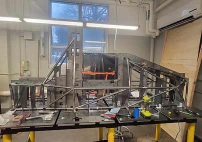
Fully Jigged Chassis

Me Celebrating a Fully Welded Chassis
Relevant Skills
SolidWorks Assemblies
Used to reference all jig features from the chassis design
Lasercutting
I manufactured all MDF parts and contributed to file preparation for many sheet steel parts