Northeastern Electric Racing: 2024 Chassis Design
I was NER's Chassis Design Lead for the 2024 competition season. I was responsible for designing the chassis to meet rules compliance, minimze weight, survive crash loads, and integrate all other projects to make a complete car. This project tested my technical skills and pushed my to learn about many other projects on the car. Feel free to read about my contributions below!
Inherited Design
The proejct had been in design for about 6 months prior to me taking responsiblility. I had previously designed the sidepods, ensuring structural compliance with the competition rules and the battery geometry requirements provided to me by the accumulator team.
Upon taking over the project, I took some time to familiarize myself with all compliance requirments associated with the chassis, as well as the integration needs from the team. This background research helped me to identify improvement areas for the design.
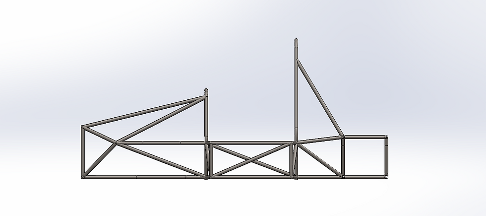
Chassis Design - End of December 2022
Drivetrain Mounting Adjustments
The drivertrain used a small rear differential to power the car. With the selected mounting, gears, and chassis geometry, the drivetrain did not fit within the chassis and the chassis was lacking required triangulation support.
I communicated with the drivetrain team, making the necessary adjustments without increaseing the wheel base, minimizing the knockdown effects experienced by other projects.
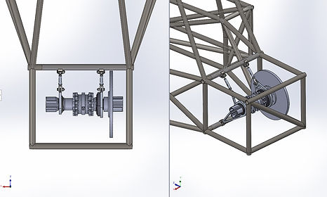
Chassis Assembly With Differential

Compliance & Organization
I completed routine compliance checks to make sure the chassis met all competition rules. There were dozens of pages of rules, so every adjustment to the chassis design had to be well maintain compliance with regards to structural, geometric, and safety requirements.
The SolidWorks part document I was given was very disorganized, so I made a new revision from scratch. I used reference planes to define the main structures of the car (bulkhead, roll hoops, rear) and 3D sketches to fill the gaps. I used feature folders to organize all frame members, as well as reference sketches & planes used to check for rules compliance.
Keeping the file organized made it easier to implement design changes and check for compliance.
Feature Tree Structure
Mid Design Review & Suspension Adjustments
I presented the chassis design in an official review to the entire engineering team for feedback. The feedback was overall positive, and mostly incuded minor changes to fulfill the needs of the team. However, the suspension team had significantly changed their design and required significant changes to their mounting geometry.
This design change affected the entire chassis, including the sidepods housing the accumulators and the section housing the drivetrain. I was careful when rearanging the geometry so the accumulators and differential could still fit while still minimizing overall chassis weight.

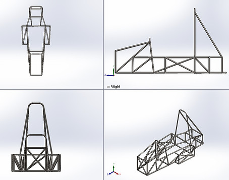
Pre-Mid Review Front View

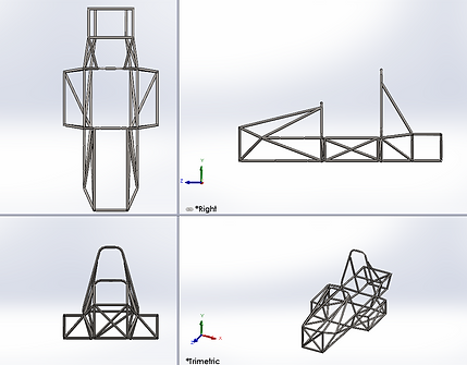
Post-Mid Review Front View

Post - Mid Design Review & Evaluation
One of the main goals for this project was a significant weight reduction. I optimized the geometry and used minimum regulation tubing sizes. Final design weighs about 80 lbs, 25% lighter than the previous chassis, crushing our weight goal.
Another strength of my design is the consideration of subsystem integraton. The last chassis did not consider the needs of the team, forcing all projects to work around the chassis. Instead, I put a lot of effort into designing 22A for the team, and I included all subsystems in chassis design conversations.
Post-Mid Review Design
Force Simulations (Finite Element Analysis)
Next, I analyzed the chassis with FEA. Using SolidWorks Simulations I tested the chassis for worst-case loading scenarios, including a 20g front impact.
In the front impact simulation, I designated the rear bulkhead as a fixed surface because the rear bulkhead would deform the least in a catastrophic front crash. This assumption was supported by research and recommendations directly from Ansys.
Initially the chassis failed the simulation with a FOS of 0.87. I using this simulation to identify weak points stress concentrations. I combined nearby nodes and increased the thicknesses of weak tubes in the design to improve strength.
I also noticed the top members along the car's length carried more stress than the bottom members. I oriented all diagonal supports in the car to redirect force from the top members to the bottom members for a more even stress distribution and improved strength.
My final design successfullt passed a 20g front impact with a FOS of 1.2 relative to its yield strength.

Initial 20g Front Impact Simulation

Final 20g Front Impact Simulation
Final Design Review & Evaluation
I led a second team-wide design review for the chassis with about 30 - 40 participating engineering students.
From this review, I developed a short list of action items related to project integrations, and locked the design soon after. The final chassis weighed 83 lbs, which is more than a 20% weight reduction. and survived all crash load simulations, incuding a 20g front impact.
Overall, this design was a huge success and great improvement over the previous chassis. I am proud of my significant contributions to the chassis design, and feel I have greatly developed my ability to work cross-functionally through this project.
Post-Final Review Design
Relevant Skills
SolidWorks Simulations
Used to ensure chassis design can survive a 20g impact and other load scenarios with no plastic deformation
SolidWorks Weldments
Used custom weldment profiles to create all chassis members
SolidWorks PDM
Used to share chassis files with the entire team and reference other project designs
SolidWorks Assemblies
Used to interface other project designs with the chassis for proper component integration